This article describes installation and configuration steps for NetFox Next Generation Firewall (NGFW). Model tested NF-EN6200.
Download manufacturer NetFox Antamedia UAM-NAS Manual
Pre-requisite:
1. Laptop / Desktop with any standard browser (IE/Chorme/Firefox/Safari)
2. Ethernet cable (Preferably CAT-6 or above)
Steps:
1. Unpack the NetFox NF Series box (Based on the choice of the model either it will be with a power adapter or built-in Power Supply Unit (PSU).
2. Power on the NGFW, you can able to hear a single beep on initial power and after 40 secs a double beep. This indicates the NGFW is booted and ready to do the initial configuration
3. For example, if you have a product with 4 Ethernet ports named Port1 – Port4 then connect the Laptop / Desktop to Port-3 using the CAT-6 cable
4. Ensure your Laptop / Desktop Ethernet Adaptor is set as “Obtain IP Automatically”
5. Open a browser and type https://192.168.100.1:4433
6. https server certificate error will occur as it has as self-signed certificate, click on “Advanced” and then click on “Accept the Risk and Continue”.
7. Login page will open and request for username & password
8. Type username as “admin” & Password as “admin99”
9. Product Dashboard screen will open with all the required details.
1. Click on the “Configuration” tab which is next to “Dashboard”. This will open up all the available configuration in product
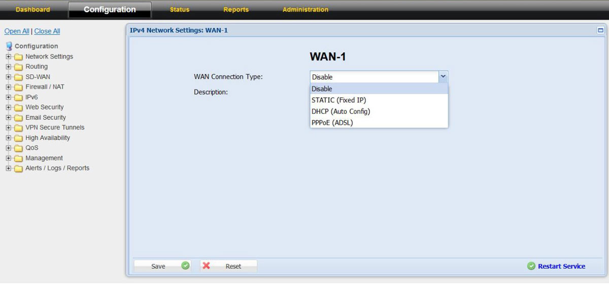
2. In “Configurations” click on “Network Settings” and choose “WAN-1”
3. Choose the WAN Connection Type as per the ISP link details either as PPPoE, DHCP, or Static
4. Do the required configuration as per the ISP link details
5. In case if you choose DHCP or in Static IP with local IP or NAT-ed IP address then
6. In the “Link Properties” on the “Link Failure Detection” option choose “Ping Remote IP” and configure Remote IP as “8.8.8.8”
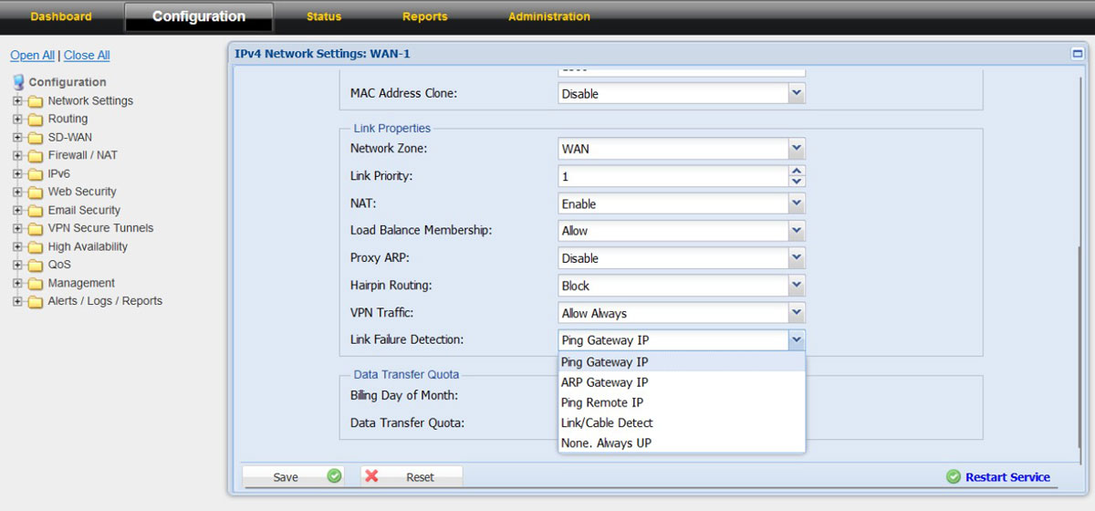
7. With this the configuration for the “WAN-1” is done, click on the “Save” and “Restart Service”
8. Connect the ISP link Ethernet cable to “PORT-1” of the NF NGFW appliance
9. Click on “Dashboard” to check whether the ISP link came up and working in the firewall

10. WAN-1 / WAN-2 status can also view from “Dashboard” – “IPV4 Port Status” from the left side tree
11. In case if the location has more than 1 Internet connection then follow the above steps to configure the second internet connection in “WAN-2” and connect the ISP link Ethernet cable to PORT-2 in the NF NFGW appliance.
1. LAN-1 is part of “Confguration – Network Settings – LAN-1 (The physical port in the NGFW appliance is PORT-3)
Please note: In case the appliance you have purchased has 6 Ethernet Port by default then the LAN-1 physical port is named as “PORT-4” in the sticker.
2. The default LAN-1 interface IP is 192.168.100.1 and the DHCP Server is enabled with DHCP pool range from 192.168.100.100 – 192.168.100.200

3. If required the LAN IP can be changed as per choice of the customer and subsequently the DHCP pool size can also be increased to meet the DHCP expected ranges.
4. Additionally, if LAN-2 (a separate LAN Segment is required can also be configured under LAN-2 configuration tab
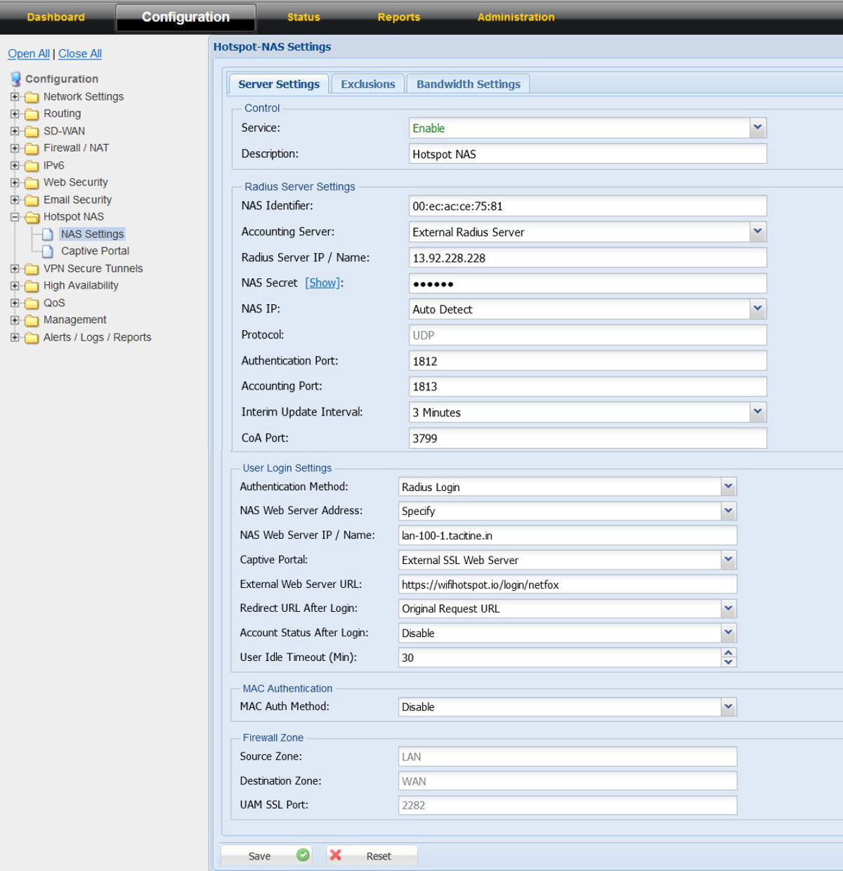
Network Access Server (NAS) / Universal Access Method (UAM)
NAS Module has 3 configurable screens
• NAS Server Settings
• Exclusions (Whitelist IP / Domains)
• Bandwidth Settings (on the ISP level)

NetFox NAS exclusion support whitelist of domains, exclusion of IPV4 IP, IPV6 IP and Source MAC.
The IP address, MAC and domains added in the exclusion list do not require authentication from Radius or in other words will work without Radius authentication.

NetFox NAS Bandwidth Settings has support to add multiple ISP connection bandwidth speeds which helps to aggregate the bandwidth and ensure the dynamic algorithm is kicking in the right time to manage the bandwidth for the guest users.
If the location has only one ISP link, then input the upload and download bandwidth of the ISP link in the Bandwidth Settings tab.
Please note: The bandwidth speed calculation is set in “kbps”

For example: If a customer has only one ISP link then do the following:
1. Click on NAS Settings – Bandwidth Settings
2. Set Bandwidth Manager as “Enable”
3. In the “Default WAN Interface Bandwidth settings “Input the Default Upload and Download bandwidth of the IPS link
4. Click on “save” and then Restart Service
In case the customer has multiple ISP links, then in the “Default WAN Interface Bandwidth Settings” add all the ISP links which is getting configured in NF Series and then input in Upload and Download bandwidth. Then click on “Configure”
1. WAN Interface Bandwidth settings will open
2. Click on “Add”
3. “Enable” the Interface
4. Choose the WAN Interface from the dropdown menu (example: WAN1, WAN2, WAN4G)
5. Input the upload and download bandwidth as per the ISP plan
6. Repeat the above for the other available ISP links configured in the NF Series firewall
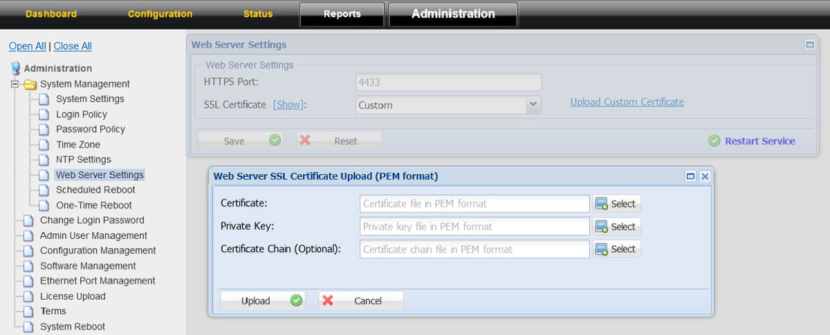
To upload the SSL Certificates
1. Click on the “Administration” tab
2. Choose System Management option in the left tree 3. Click on Web Server Settings 4. Click on “Upload Customer Certificate”
5. Upload the relevant certificate, Private key and Certificate Chain