NetFox NGFW
This article describes installation and configuration steps for NetFox Next Generation Firewall (NGFW). Model tested NF-EN6200.
1. The integration is available for NetFox NF Series of Next Generation Firewall (NGFW) only
2. Support on NF-10 Series of SDWAN Routers not available
3. NAS add on license is required in NF-Series to do the necessary configuration for the Radius integration
4. NF Series is a NGFW product built with Routing, DPI Firewall, Web Security and VPN Modules along with NAS (UAM) integration add on module
Download manufacturer NetFox Antamedia UAM-NAS Manual
NF Series – Basic Configuration
Pre-requisite:
1. Laptop / Desktop with any standard browser (IE/Chorme/Firefox/Safari)
2. Ethernet cable (Preferably CAT-6 or above)
Steps:
1. Unpack the NetFox NF Series box (Based on the choice of the model either it will be with a power adapter or built-in Power Supply Unit (PSU).
2. Power on the NGFW, you can able to hear a single beep on initial power and after 40 secs a double beep. This indicates the NGFW is booted and ready to do the initial configuration
3. For example, if you have a product with 4 Ethernet ports named Port1 – Port4 then connect the Laptop / Desktop to Port-3 using the CAT-6 cable
4. Ensure your Laptop / Desktop Ethernet Adaptor is set as “Obtain IP Automatically”
5. Open a browser and type https://192.168.100.1:4433
6. https server certificate error will occur as it has as self-signed certificate, click on “Advanced” and then click on “Accept the Risk and Continue”.
7. Login page will open and request for username & password
8. Type username as “admin” & Password as “admin99”
9. Product Dashboard screen will open with all the required details.
Configuring WAN (Internet Service Provider – Links)
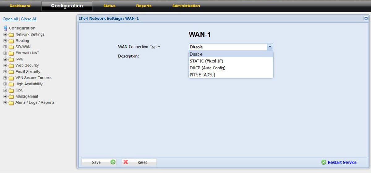
1. Click on the “Configuration” tab which is next to “Dashboard”. This will open up all the available configuration in product
2. In “Configurations” click on “Network Settings” and choose “WAN-1”
3. Choose the WAN Connection Type as per the ISP link details either as PPPoE, DHCP, or Static
4. Do the required configuration as per the ISP link details
5. In case if you choose DHCP or in Static IP with local IP or NAT-ed IP address then
6. In the “Link Properties” on the “Link Failure Detection” option choose “Ping Remote IP” and configure Remote IP as “8.8.8.8”
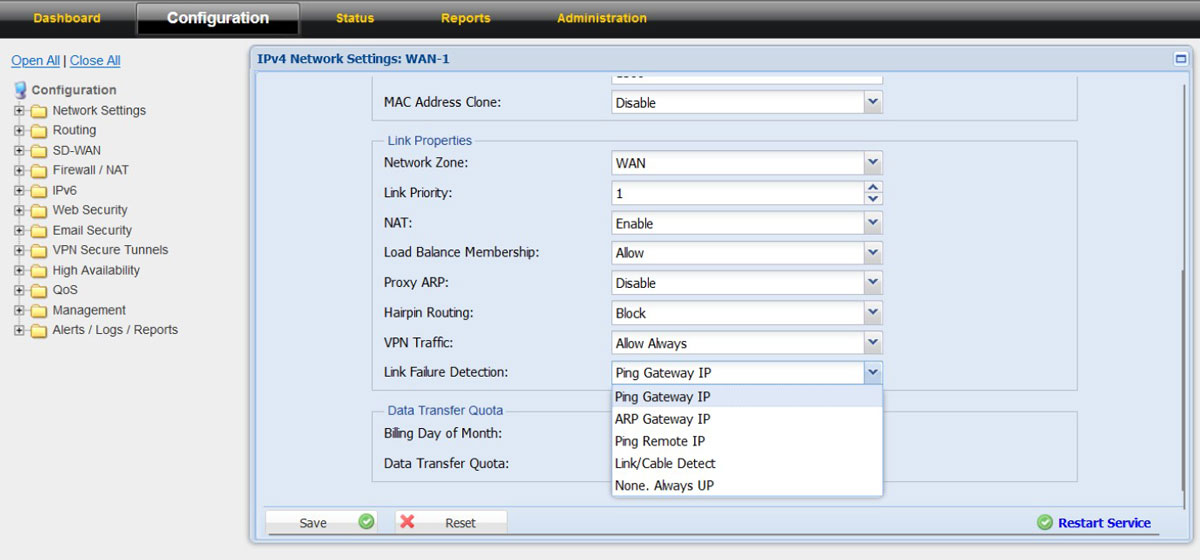
7. With this the configuration for the “WAN-1” is done, click on the “Save” and “Restart Service”
8. Connect the ISP link Ethernet cable to “PORT-1” of the NF NGFW appliance
9. Click on “Dashboard” to check whether the ISP link came up and working in the firewall
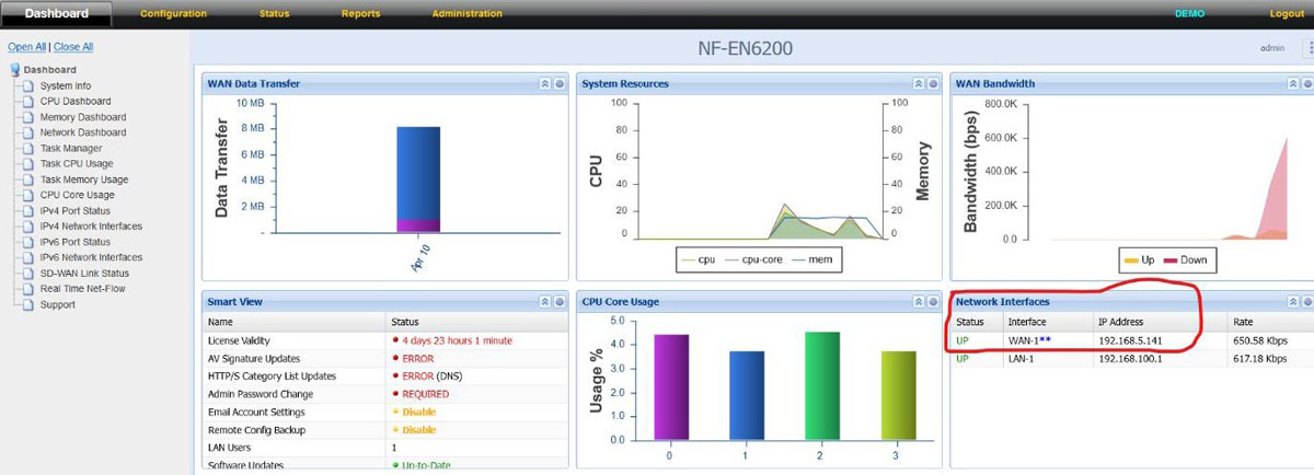
10. WAN-1 / WAN-2 status can also view from “Dashboard” – “IPV4 Port Status” from the left side tree
11. In case if the location has more than 1 Internet connection then follow the above steps to configure the second internet connection in “WAN-2” and connect the ISP link Ethernet cable to PORT-2 in the NF NFGW appliance.
Configuring LAN (Local Area Networks – Links)
1. LAN-1 is part of “Confguration – Network Settings – LAN-1 (The physical port in the NGFW appliance is PORT-3)
Please note: In case the appliance you have purchased has 6 Ethernet Port by default then the LAN-1 physical port is named as “PORT-4” in the sticker.
2. The default LAN-1 interface IP is 192.168.100.1 and the DHCP Server is enabled with DHCP pool range from 192.168.100.100 – 192.168.100.200
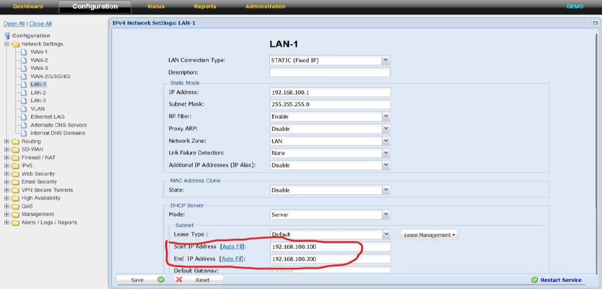
3. If required the LAN IP can be changed as per choice of the customer and subsequently the DHCP pool size can also be increased to meet the DHCP expected ranges.
4. Additionally, if LAN-2 (a separate LAN Segment is required can also be configured under LAN-2 configuration tab
Configuring UAM – Hotspot NAS Module
Network Access Server (NAS) / Universal Access Method (UAM)
NAS Module has 3 configurable screens
• NAS Server Settings
• Exclusions (Whitelist IP / Domains)
• Bandwidth Settings (on the ISP level)
NAS Settings: Server Settings
Control
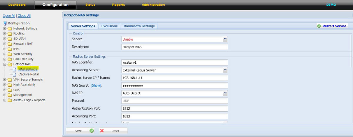
Service – Checkbox used to enable or disable the NAS Module. The NAS module is enabled when the checkbox is selected
Description – Relevant name to identify the NAS Module
NAS: Server Settings Radius Server Settings
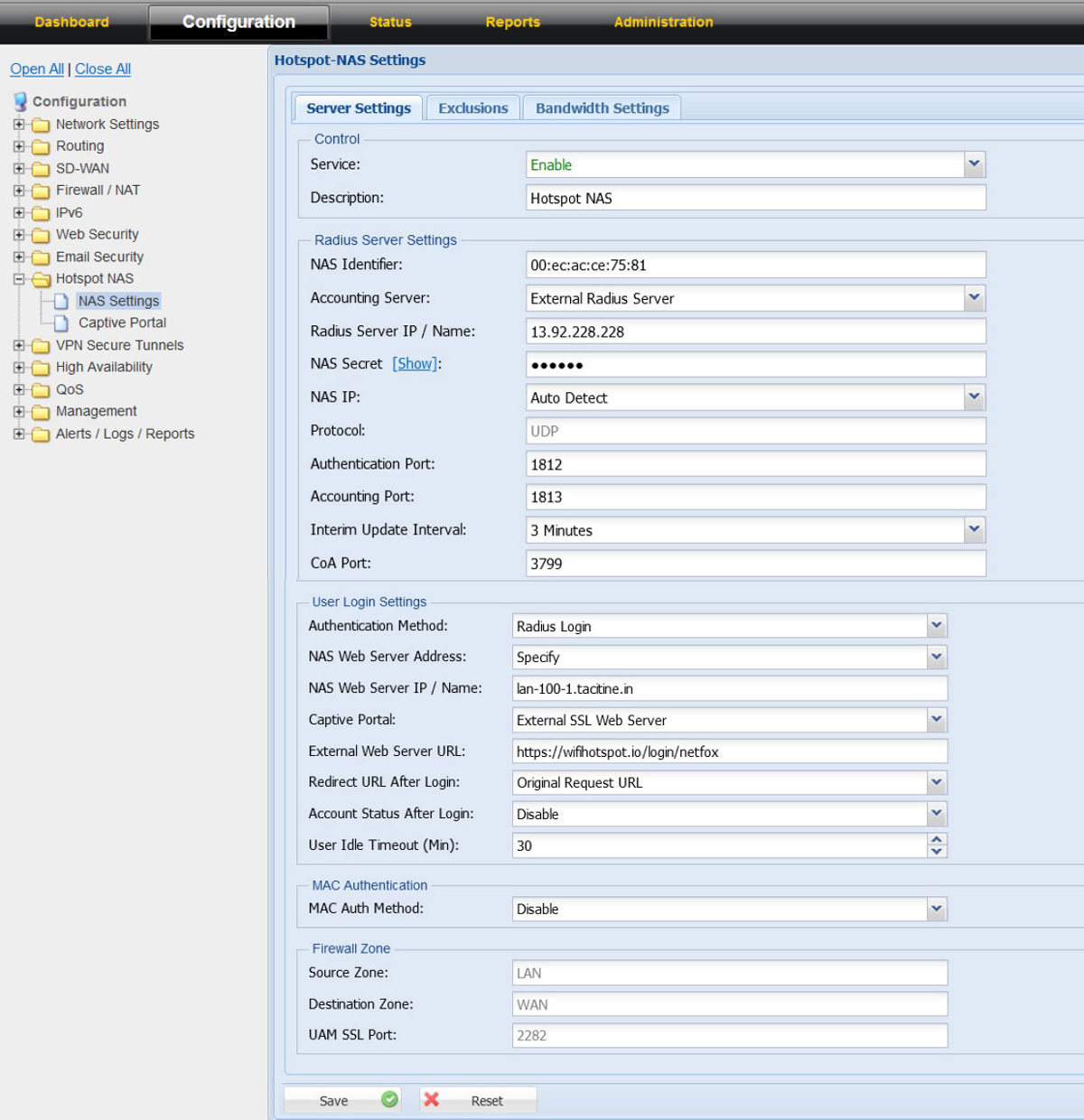
NAS Identifier – Identifier used to identify the UAM / NAS to post the details back from Radius Server
Values: Name or MAC address
Example: Name: ANTAMEDIA-BLR | MAC: 00:0A:00:00:00:00
Accounting Server – External Radius Server
Americas Server:
Radius Server IP / Name – 13.92.228.228
Authentication Port – 1812
Accounting Port –1813
Europe & Global Server:
Radius Server IP / Name – 109.245.64.94
Authentication Port – 1812
Accounting Port – 1813
NAS Secret – Contact our office
NAS IP – IP address of the UAM / NAS
Supported Values: Auto Detect | Specify
On choice of specify the IP address of the NAS can be configured
Protocol – UDP
Interim Update Interval – Time interval in which the UAM/NAS provide usage information to Radius server
Values: max up to 10 minutes | Default: 3 mins
CoA Port – 3799 (Standard Port)
NAS: Server Settings User Login Settings
Authentication Method – Radius Login
NAS Web Server Address – Values: Auto Detect & Specify | Default: Auto Detect
On choice of specify the IP / Name of the NAS web server can be configured
Captive Portal
Values:
Internal Web Server (Port 80)
Internal SSL Web Server (Port 443)
External Web Server (Port 80)
External SSL Web Server (Port 443)
Choose – External SSL Web Server
External web server URL to be configured is https://wifihotspot.io/login/netfox
Internal Web Server Port – 2280 (This is the port use by NAS to communicate to the guest users)
Redirect URL after login
Values:
Original Request URL
Specify Redirect URL
Welcome URL
the Redirect URL after login is controlled by the Radius server
Account Status after login
Values:
1. Show in Popup Window (Pop up windows with login successful message along with time, reset password option (user details)
2. Disable
It is advisable to configure as “Disable” as most of the apple IOS wont support show in pop window
User Idle Timeout(min) – Values: From 5 – 14400 mins | Default:30 mins
NAS: Server Settings Server Settings: MAC authentication
MAC Authentication Method
Values:
Disable
MAC as username
MAC as username and password
Default: Disable
NAS: Server Settings Firewall Zone (not editable)
Source Zone – LAN
Destination Zone – WAN
UAM Port – 2281
NAS Settings: Exclusion (Whitelist)
NetFox NAS exclusion support whitelist of domains, exclusion of IPV4 IP, IPV6 IP and Source MAC.
The IP address, MAC and domains added in the exclusion list do not require authentication from Radius or in other words will work without Radius authentication.
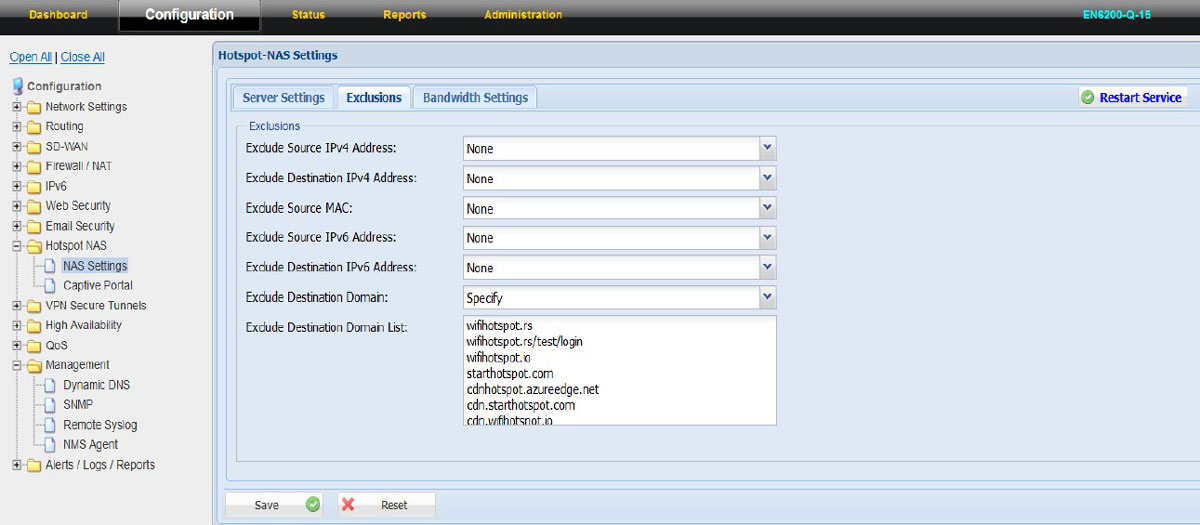
NAS: Exclusions Exclude Source IPV4 address – Values: None | Specify
For IP to exclude from Radius Authentication please choose “Specify” and add the IPV4 IP address
Exclude Destination IPV4 address – Values: None | Specify
For the destination IPs to get exclude from Radius Authentication please choose “Specify” and add the IPV4 Destination IP address
Exclude Source MAC – Values: None | Specify
To exclude source MAC address of a selected devices choose “Specify” and add the MAC address
Exclude Source IPV6 address – Values: None | Specify
For IP to exclude from Radius Authentication please choose “Specify” and add the IPV6 IP address
Exclude Destination IPV6 address – Values: None | Specify
For the destination IPs to get exclude from Radius Authentication please choose “Specify” and add the IPV6 Destination IP address
Exclude Destination Domain – Values: None | Specify
To whitelist domains from Radius server authentication choose “Specify” and input the domain names
The domains that should be whitelisted from UAM-NAS module:
antamedia.net
app.antamedia.net
app.antamedia.com
wifihotspot.io
static.cloudflareinsights.com
13.92.228.228
109.245.64.94
91.150.99.187
ocsp.sectigo.com
ocsp.usertrust.com
ocsp.comodoca.com
crl.sectigo.com
crl.usertrust.com
crl.comodoca.com
crt.sectigo.com
crt.usertrust.com
crt.comodoca.com
apple.com
sectigo.com
usertrust.com
NAS Settings: Bandwidth Settings
NetFox NAS Bandwidth Settings has support to add multiple ISP connection bandwidth speeds which helps to aggregate the bandwidth and ensure the dynamic algorithm is kicking in the right time to manage the bandwidth for the guest users.
If the location has only one ISP link, then input the upload and download bandwidth of the ISP link in the Bandwidth Settings tab.
Please note: The bandwidth speed calculation is set in “kbps”
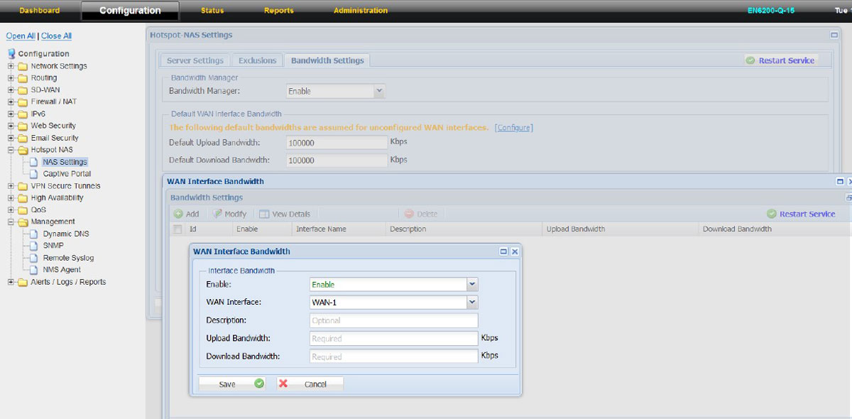
For example: If a customer has only one ISP link then do the following:
1. Click on NAS Settings – Bandwidth Settings
2. Set Bandwidth Manager as “Enable”
3. In the “Default WAN Interface Bandwidth settings “Input the Default Upload and Download bandwidth of the IPS link
4. Click on “save” and then Restart Service
In case the customer has multiple ISP links, then in the “Default WAN Interface Bandwidth Settings” add all the ISP links which is getting configured in NF Series and then input in Upload and Download bandwidth. Then click on “Configure”
1. WAN Interface Bandwidth settings will open
2. Click on “Add”
3. “Enable” the Interface
4. Choose the WAN Interface from the dropdown menu (example: WAN1, WAN2, WAN4G)
5. Input the upload and download bandwidth as per the ISP plan
6. Repeat the above for the other available ISP links configured in the NF Series firewall
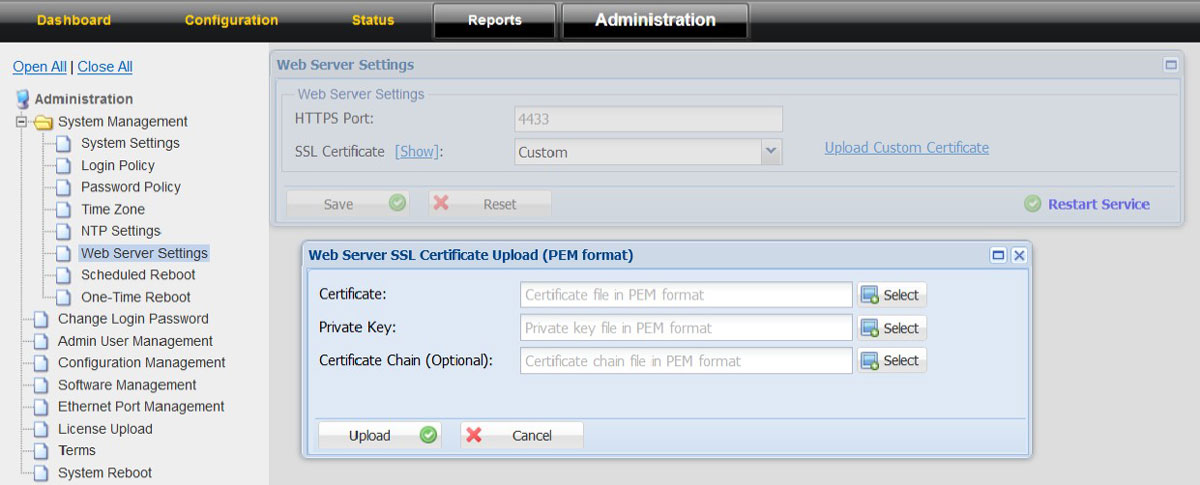
Option to upload SSL Certificates
To upload the SSL Certificates
1. Click on the “Administration” tab
2. Choose System Management option in the left tree 3. Click on Web Server Settings 4. Click on “Upload Customer Certificate”
5. Upload the relevant certificate, Private key and Certificate Chain